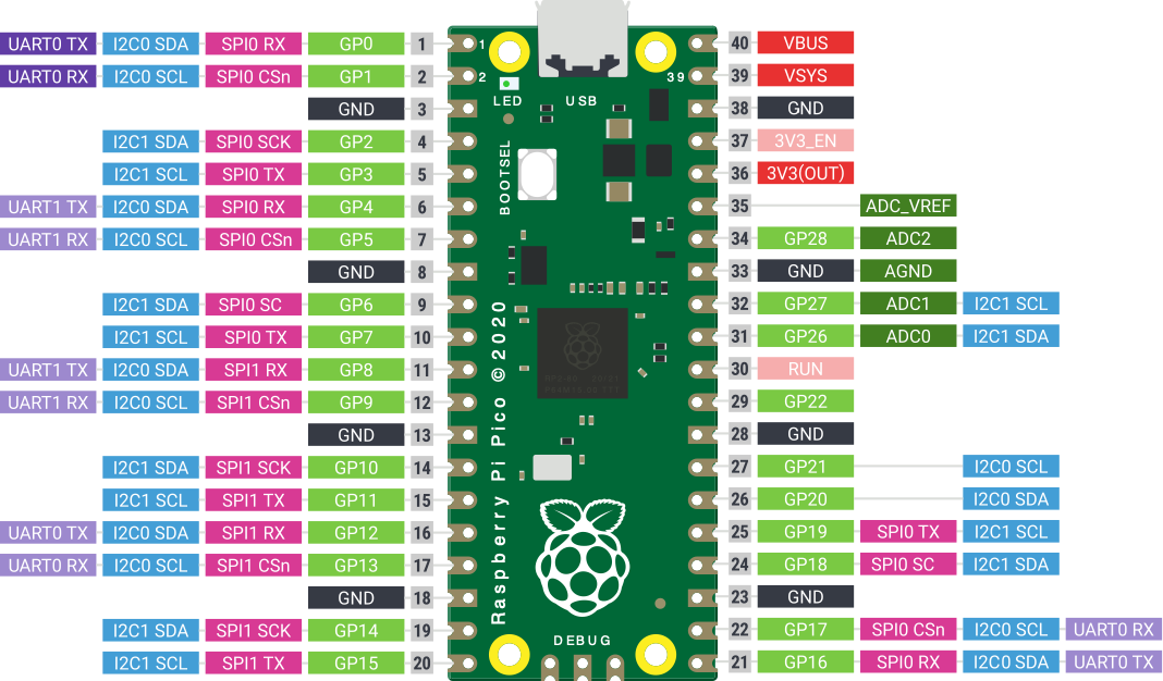
Pico Pinouts
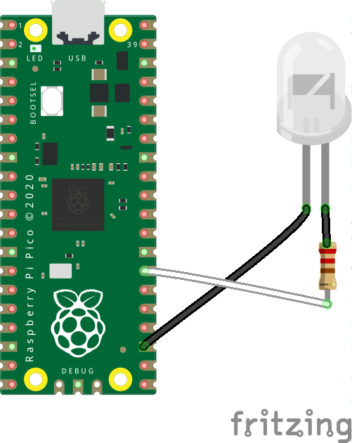
Because we need a pin to attach a Led
Or, yet another clock.
When you booted this thing without disks it booted into "Cassette Basic"
| Ram Memory: | 16Kb to 640Kb Max |
| Storage: |
320Kb per Disk |
| Cpu Speed: |
4.77 MHz |
| Cost: |
~$6000 No Tax or shipping - includes software
and printer ($17,000 today) |

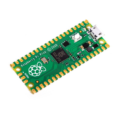
When you boot this it boots into MMBasic a "clone" of Microsoft Basic
| Ram Memory: |
264Kb |
| Storage: |
2Mb |
| Cpu Speed |
125MHz dual core |
| Cost: |
$10 with tax and shipping |
- Download the firmware (includes the Amazing Documentation above) from https://geoffg.net/Downloads/picomite/PicoMite_Firmware.zip to a new directory of your choice - perhaps picoBasic.
- Unzip the downloaded file.
- Hold down the boot button on the Pico and plug in the USB cable to the computer that you downloaded the firmware file. This will present the Pico as a remote disk.
- Copy the file PicoMiteV5.07.04.uf2 (your version may vary) to the "remote disk".
- When the copy is done the Pico will reboot and the onboard Led will start to blink.
https://rfc1149.net/blog/2013/03/05/what-is-the-difference-between-devttyusbx-and-devttyacmx/
To connect my terminal app to the desired tty use:
screen /dev/ttyACM0
print "hello, world"
Because the first time I saw a loop in a computer language I was beside myself with excitement.
for num = 0 to 20 step 2
print num
next num
Pico Pinouts
Because we need a pin to attach a Led
' Loop blinking led
SetPin gp21, dout
Do
Pin(gp21) = 1
Pause (300)
Pin(gp21) = 0
Pause (700)
Loop
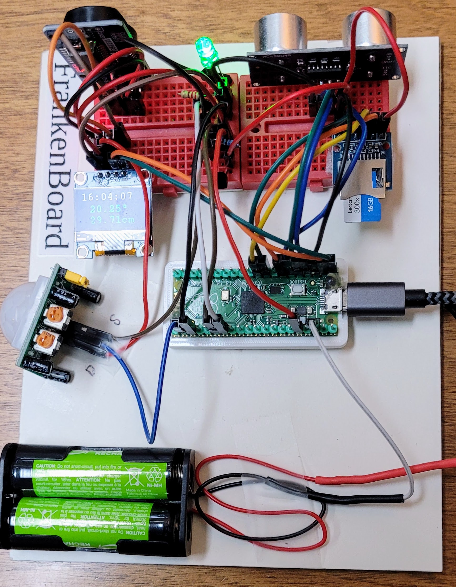
It started out with hello world. Then flashing a led then measuring temperature and displaying it on the terminal, because that was easy. Next displaying the time and temperature on the terminal, because one needs to know when. Then a Oled screen to show the time and temperature. But still I needed to enter the time on boot. So I needed to add a real time clock. Next a distance sensor and a PIR detector. And, last a SD card reader writer.
And it was all easy Geoff Graham and folks have done an amazing job on this software and documentation.
(not the breadboard below - that's my fault)
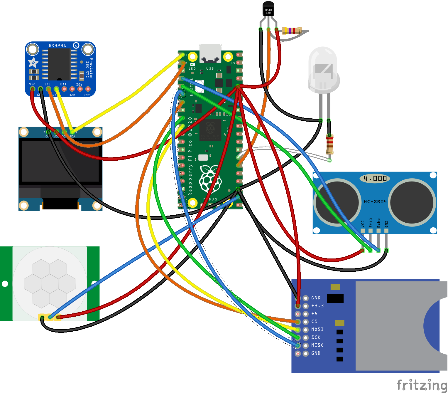
Introducing the FrankenBoard ...
There are 7 flash storage locations for programs 1-7.
Some of the FLASH commands:

Simply: PRINT "Temperature: " TEMPR(pin)
For my system:
print Tempr(gp20)
' Blink loop, temperatureAnd then time and temperature ...
Print "hello blinking world. The temperature:"
SetPin gp21, dout
Do
Pin(gp21) = 1
Pause 300
Pin(gp21) = 0
Pause 700
Print TEMPR(gp20)
Loop
Do
Pin(gp21) = 1
Pause 300
Pin(gp21) = 0
Pause 700
print TIME$
Print TEMPR(gp20)
Loop
From the documentation:
OPTION SYSTEM I2C SDApin, SCLpin
OPTION LCDPANEL SSD1306I2C, OR [,offset]
"Initialises a OLED display using the SSD1306 controller with an I2C interface. This supports 128 * 64 resolution. An additional parameter offset may be specified to control the position of the display. 0.96" displays typically need a value of 0. 1.3" displays typically need a value of 2. Default if omitted is 0. NB many cheap I2C versions of SSD1306 displays do not implement I2C properly due to a wiring error. This seems to be particularly the case with 1.3" variants"
For my system:
option system i2c, 1, 2When you execute the above commands the pico will reboot - for both of the commands.
option lcdpanel ssd1306i2c, landscape
The Y.A.C. (yet another clock)
' Set the font size and clear the Oled screen
Font 2
CLS
' Subroutine to blink the led
Sub blink ontime, offtime
Pin(gp21) = 1
Pause ontime
Pin(gp21) = 0
Pause offtime
End Sub
' Print hello and set the led pin to output
Print "hello cool world. The temperature is:"
SetPin gp21, dout
' Loop forever ^C will stop
Do
' Blink the led
blink(300, 700)
' Display the time and temperature
Print "Time: " + Time$
' Get the temperature and adjust
t = TEMPR(gp20) + 3
ts$ = Str$(t, 0, 2)
Print "Temperature: " + ts$
' Display the time and temperature on the Oled
Text 5, 0, Time$
Text 20, 25, ts$
Loop
We don't want to have to enter the time on boot. No
additional code is required. Just turn on the option to read
the RTC on boot. This will initialize the time$ system
variable when the Pico is booted.
option rtc auto enableI was a bit nervous about adding the RTC since both the Oled and the RTC are I2C devices and nowhere are addresses specified. I guess MMBasic figures it out from the addresses presented.
0x3c |
SSD1306 SH1106 PCF8569 PCF8578 PCF8574AP SSD1305 |
|---|
0x3d |
SSD1306 SH1106 PCF8578 PCF8574AP SSD1305 |
|---|
0x68 |
PCA9685 AMG8833 DS1307 PCF8523 DS3231 MPU-9250 ITG3200 PCF8573 MPU6050 ICM-20948 WITTY PI 3 MCP3422 DS1371 |
|---|
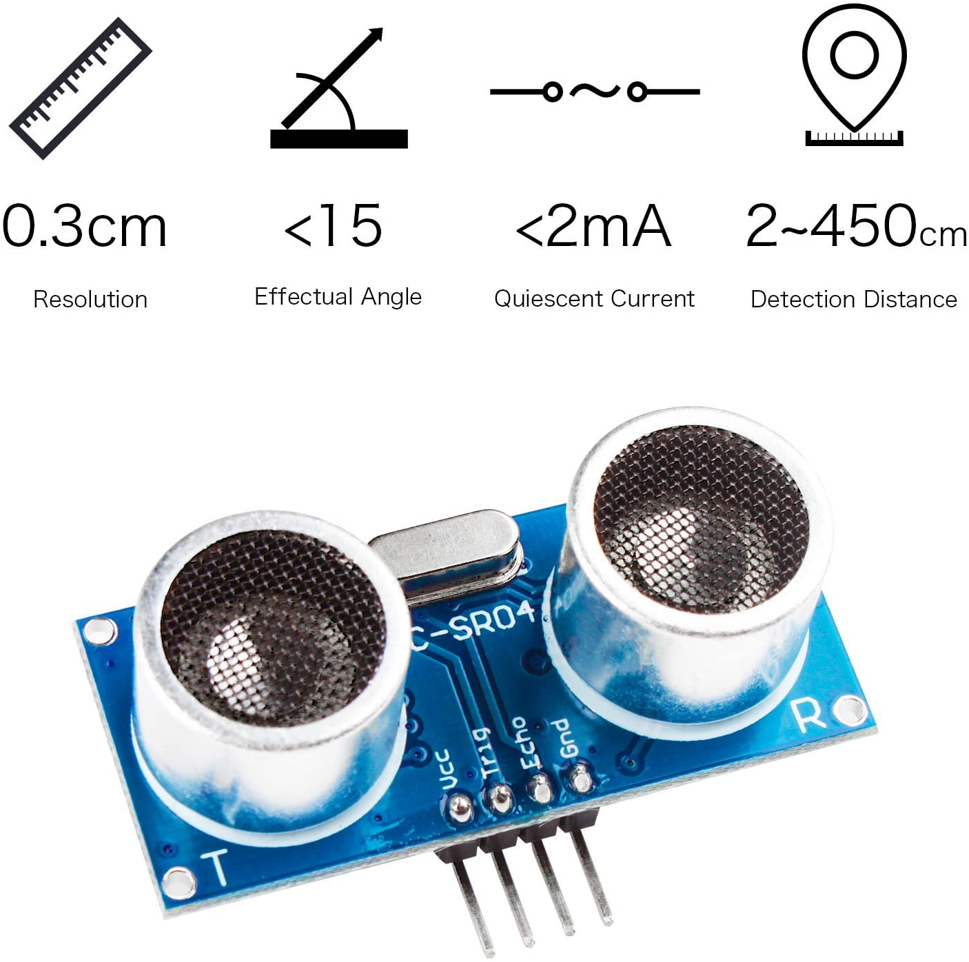
and the command to read it is
distance(trigger pin, echo pin)
on my system:
distance(5, 4)
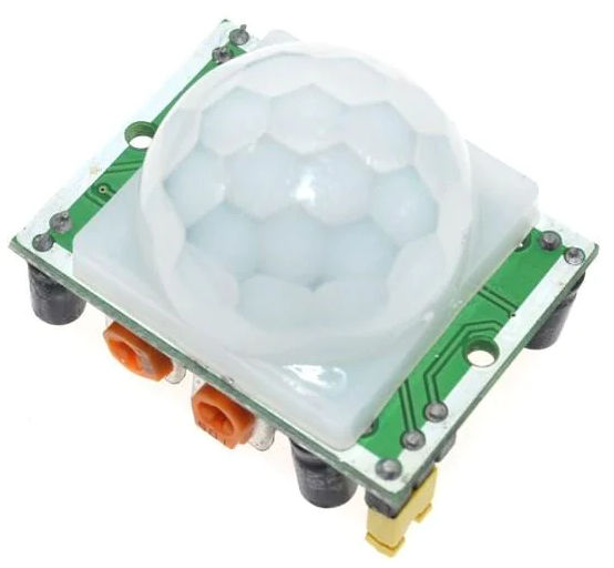
HC-SR501 Module
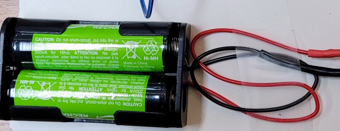
The battery so it can run stand alone
The Pico will run from 1.8V to 5.5V. An onboard Switched Mode Power Supply (SMPS) will condition this to the required 3.3V. The battery connects to the VSYS pin which feeds the SMPS.
Now I had to measure the voltage on the battery. The VSYS voltage/3 is available via an analog input on pin 44
print Pin(44) * 3
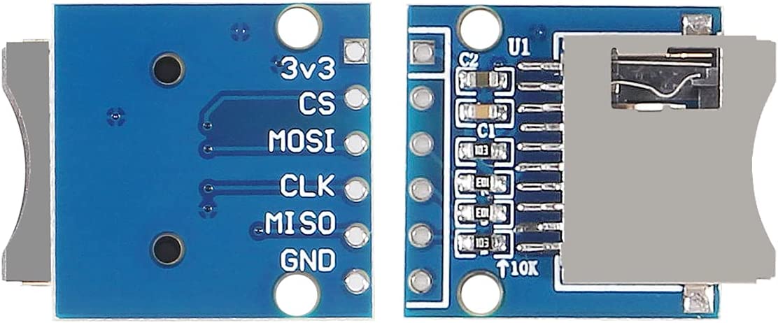
Wire it up and set the following options. They will cause
the Pico to reboot.
OPTION SYSTEM SPI GP6,GP7,GP4
OPTION SDCARD GP5
Examples
> files
A:/basic
12:44 24-10-2022 63 prog1.bas
12:44 24-10-2022 126 prog2.bas
12:45 24-10-2022 190 prog3.bas
12:45 24-10-2022 668 prog4.bas
12:41 24-10-2022 2405 prog6.bas
0 directories, 5 files
> chdir ".."
> list "blink.bas"
> files
A:/
<DIR> basic
00:04 28-09-2022 204 blink.bas
21:31 17-10-2022 48 loop.bas
12:24 24-10-2022 2405 prog6.bas
17:26 13-10-2022 230 tblink.bas
17:24 13-10-2022 655 yac.bas
1 directory, 5 files
Option autorun on> load "loop.bas"
Option colourcode off
Sub blink ontime, offtime
Pin(gp21) = 1
Pause ontime
Pin(gp21) = 0
Pause offtime
End Sub
Print "hello world"
SetPin gp21, dout
Do
blink 300, 600
Loop
> list
For num = 0 To 20 Step 2
Print num
Next num
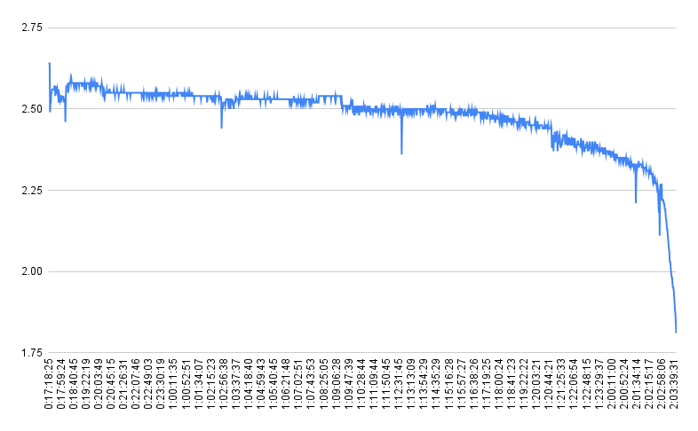
Since I have an SD card to put stuff on, why not save the battery
voltage for a while. In this case until the Pico stops.
Nickel Metal Hydride (NiMH) two AA cells.
We are going to use sx (xmodem send) to get a file from the
host to the Pico
apt install lrzszThen on the Pico terminal:
The following options have been set to enable the behaviour that
has been discussed